Sunday, October 29, 2006

More brake stuff


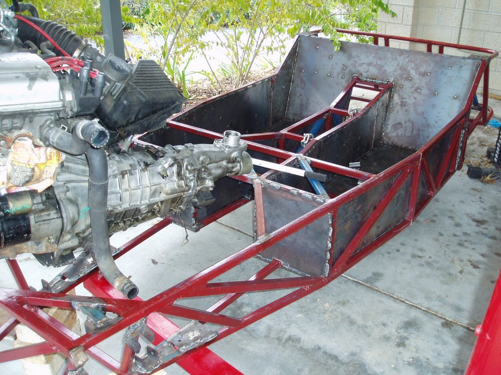
Spent some more time working on the brakes. Finally got the brake booster in. I created a bit of plate which was welded to the pedal box mounting frame. I did a quick measurement and it looks like the booster will not be in the way of other things. I wont know until I re-mount the engine.

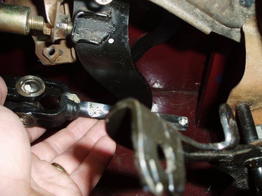
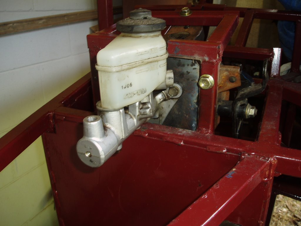
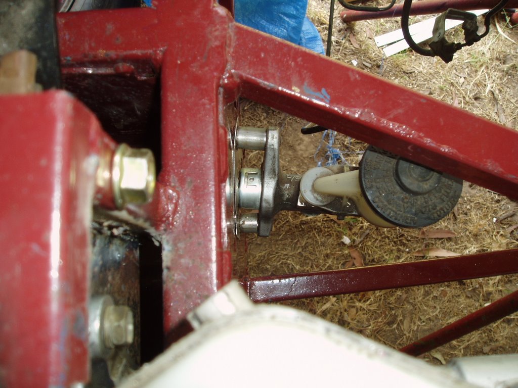
I have also mounted the clutch master cylinder. It is reasonably low on the pedal. I am hoping this will not create to "heavy" a clutch. It is about 4/5 the way down, the original toyota was 1/5 the way down, the pedal. From the pictures you can see I am stuck with this configuration unless I get out the grinder and move a structural member in the engine bay. If the clutch ends up being to heavy I will relocate it. The clutch master cylinder is also mounted on a slight angle, this is so i get a smooth clutch compression as the pedal runs on a slight angle.

Next job is to get the diff cleaned and painted. Also to start mounting the brake lines and fuel lines. Once this is done I can put it back on wheels and start the task of wiring / re-wiring the motor, dash and body.

Monday, October 16, 2006

The brake stuff


Wow the second post in the same night. I must be busy (I wish progress was as good as the posts). So what we have in these pics is the brake master cylinder and the push rod that activates it. Also you can see a bolt being measured. This is roughly the size that the other end of the push rod fits for the cylinder.

To my suprise and thanks to Charles it looks like this step is going to be a lot less painful than first thought. I was thinking I would need to fabricate something that fitted a 10 mm bolt thread and then fit a tube to a spring to create something to spring back the 6-ish mm head that fitted into the master cylinder from the orignal brake booster unit. The pedal should take care of the spring back.

The basic idea going to be used is to take a 10mm bolt of the correct length. I am thinking this will need to be at least 100 mm but should be less than 140 mm long (more measuring required). Cut the head off it and round it out to fit the master cylinder. I will chop the front of the old brake booster (not pictured) to give me a mounting plate for the master cylinder. This plate will be welded to the car frame to stop it moving.

Sounds simple, hopefully the execution is as good as the description.

The steering mounted


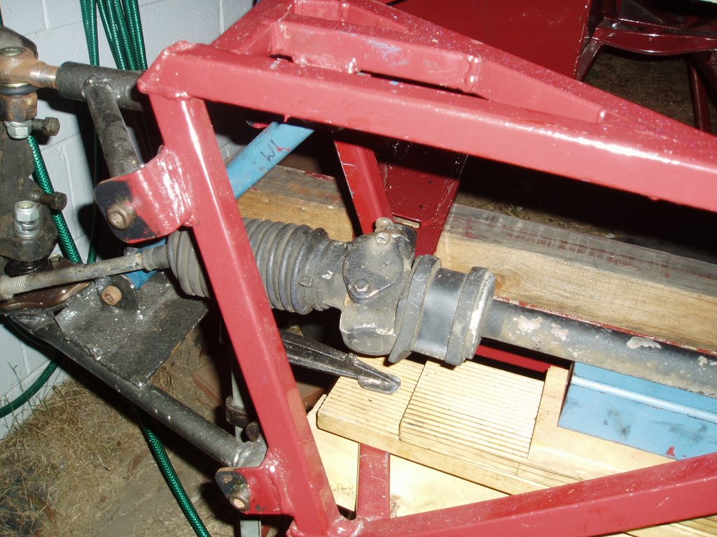
Well here is the steering rack mounted. It looks a little high and to far forward. The problem is that the springs (the blue steel) will be in the way if it is moved further back. After some discussion and more research it looks like the above rack is to big. It is a cortina rack in a 100+ frame. The reason it seems to big is my location of the rack is very limited (I should have pushed the springs outside the frame not inside) this means that the joint in the rack is outside the plane of the arm rotation. I am hoping that an escort rack will solve the problem. I will need to make sure I get all the bits this time. eg: All the rubbers, the rod back to the column and any extra CV joints.

Also in these photos I have attempted to take photos of where I think the column will go through the firewall. Although it is not ideal, it looks like I will need 3-4 uni joints and a bit of magic matching them. This is yet to be worked out, but the general idea is that it will come through the wall about half way down and over to the right of the wall. It should all make sense once I cut the hole and push the rods through.

Monday, September 25, 2006

Finally a full undercoat


Well it is red, very very red. "Indian red" to be exact. Most of it will be covered but just enough will show through for an interesting contrast to the final body colour (A well kept secret). Since making it home, I have removed the engine and wheels. Put it on "bricks", well horses is more like it, and starting adding the bits to make it drivable.

As can be seen from the photos, the driver has somewhere to sit (spiderman is already putting a claim to that seat - hopefully I can talk him into being the navigator), and the steering is in. The pedals have been mounted but not in situ in any of the pictures. Sitting in it, the seating position feels nice and everything seems in the correct place. A keen eye will notice the pedal mounts are on a slight angle, this is by design to ensure that both the brake pedal and steering are centered in the car. The angle also stops the clutch pedal from hitting the firewall, this saved me from having to modify the box. I am still not sure if I will hide it or make it a "feature", when putting the ali in engine bay.
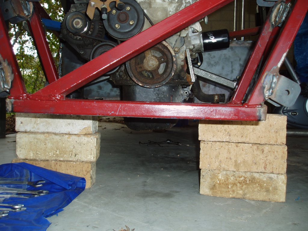
I have also almost finished welding the fuel tank, hopefully it turns out. Planing on using POR15 to seal any holes created from the welding process. It is the rusty looking thing in the top photo and yes that is the final location. I expect it to hold just under 40 Ltrs. If I get around to it I will post pictures of the jig for the sliding rails for the seat and the tank jig (an empty beer carton).

Plans for the upcoming month is to strip the brake booster back to just the insides. eg: No vacuum boost. Modify it to fit the Honda pedals and the Toyota bits taken from the half cut. Finish the fuel tank, get the steering rack into the correct position and run fuel and brake lines. Then i can go back to putting it on wheels, the engine in and running the electrics (That is where the real fun comes in).

Hopefully the progress and the updates will be a little more regular.

Saturday, August 05, 2006

The pedals


Got these out of a honda civic ED (I think). Hopefully they should fit into the 100+ frame without to many mods.

Its home


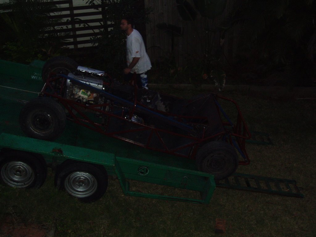
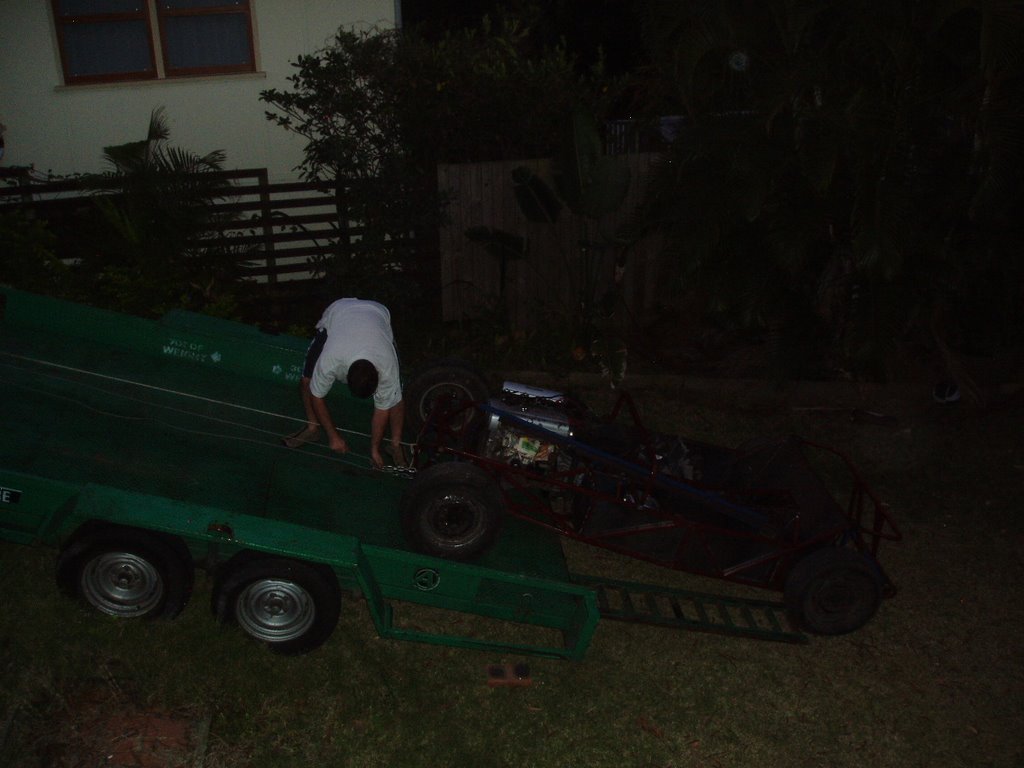
The car has finally come home. It as interesting getting it on and off the car trailer. We had to park it on an angle as the clearance is so low that the gearbox was hitting the trailer as it was loaded on. i didn't want to have the same problems unloading.

Beaming and Torsion


The car is finally ready for the beaming and torsion test. Here are a couple of pics of it setup. Forgot the camera on the actual test day. So it looks like this is all I have of the test rig. From memory it was loaded with 175 kg for the torsion and beaming was 86Kg in each side.

I am still waiting for the results from the engineer but from my calcs it looks like it passed with flying colours.

Friday, August 04, 2006

Engine refit


Had to refit the engine to finish off the last of the structual things around the engine bay. Another day of messing around resulting in two bits of steel being welded.